Howdy, Stranger!
We are about to switch to a new forum software. Until then we have removed the registration on this forum.
Categories
- All Categories 25.7K
- Announcements & Guidelines 13
- Common Questions 30
- Using Processing 22.1K
- Programming Questions 12.2K
- Questions about Code 6.4K
- How To... 4.2K
- Hello Processing 72
- GLSL / Shaders 292
- Library Questions 4K
- Hardware, Integration & Other Languages 2.7K
- Kinect 668
- Arduino 1K
- Raspberry PI 188
- Questions about Modes 2K
- Android Mode 1.3K
- JavaScript Mode 413
- Python Mode 205
- Questions about Tools 100
- Espanol 5
- Developing Processing 548
- Create & Announce Libraries 211
- Create & Announce Modes 19
- Create & Announce Tools 29
- Summer of Code 2018 93
- Rails Girls Summer of Code 2017 3
- Summer of Code 2017 49
- Summer of Code 2016 4
- Summer of Code 2015 40
- Summer of Code 2014 22
- p5.js 1.6K
- p5.js Programming Questions 947
- p5.js Library Questions 315
- p5.js Development Questions 31
- General 1.4K
- Events & Opportunities 288
- General Discussion 365
In this Discussion
- _vk November 2015
- BarbaraAlmeida February 2016
- blindfish December 2015
- Casey_Scalf December 2015
- chrleon December 2015
- KevinWorkman December 2015
- kpfeiffer November 2015
- rapatski February 2016
Stroke Outside, Or Inside - Not Both?

I have been working with some strokes around shapes I made using a vertex.
Lets use the popular star shape as an example code. Any irregular shape is of interest.
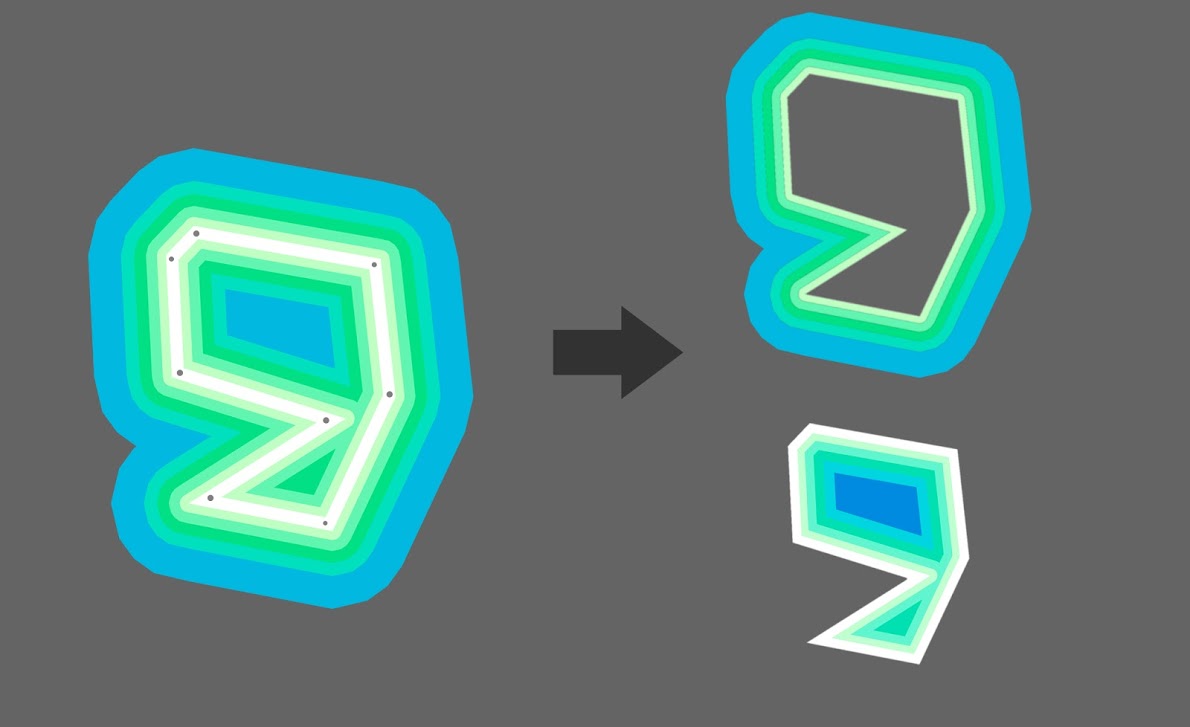
How can I use stroke() so that the stroke is only applied to the inner edge? Or only the outer edge? See picture.
This is a popular tool when using vectors in Illustrator or Photoshop so I thought I might have a chance at communicating this and illustrating the desired outcome.
Thanks for any tips!
// How to make it so stroke is only drawn on one side of edge?
void draw() {
  background(51);
  translate(mouseX, mouseY);
  fill(102);
  stroke(255);
  strokeWeight(2);
  beginShape();
  vertex(0, -50);
  vertex(14, -20);
  vertex(47, -15);
  vertex(23, 7);
  vertex(29, 40);
  vertex(0, 25);
  vertex(-29, 40);
  vertex(-23, 7);
  vertex(-47, -15);
  vertex(-14, -20);
  endShape(CLOSE);
}
Tagged:
Answers
Can you post an example image showing the effect you're going for?
You mean the thin gray hair-line beyond the white stroke? What happens if you use this feature in AI export it, and import in Processing?
I'm afraid Processing doesn't do this. To be fair I wouldn't even know how you'd do it if you were to program the behaviour from scratch. Processing does allow you to change caps and joins.
Oh and regarding the star.. Sorry, couldn't resist.. You're a programmer now!
float rotation = 0; void draw() { background(51); translate(mouseX, mouseY); // star fill(102); stroke(255); strokeWeight(2); beginShape(); vertex(0, -50); vertex(14, -20); vertex(47, -15); vertex(23, 7); vertex(29, 40); vertex(0, 25); vertex(-29, 40); vertex(-23, 7); vertex(-47, -15); vertex(-14, -20); endShape(CLOSE); // new star stroke(255, 0, 0); drawStar(0, 0, 5, 20, 40, rotation); rotation += 0.01; } void drawStar(float x, float y, int numPoints, float innerRadius, float outerRadius, float angleOffset) { float dAngle = TWO_PI/numPoints; beginShape(); for(int i = 0; i < numPoints; i++) { float px, py, angle; // outer points angle = i*dAngle + angleOffset; px = outerRadius*cos(angle); py = outerRadius*sin(angle); vertex(x + px, y + py); // innver points angle = (i + 0.5)*dAngle + angleOffset; px = innerRadius*cos(angle); py = innerRadius*sin(angle); vertex(x + px, y + py); } endShape(CLOSE); }Thanks for the replies.
@KevinWorkman, please see the picture in original post.
To detail that, you can see the grey points. The white line is what is normally drawn. On the right are what might be a "inner only version" and an "outer only" version of the points "stroked" a little differently.
The code I posted, although a star, is to show what kind of code I'm trying to draw. I made an irregular shape because you can't scale the points and have it look right. It has to be a quasi-intelligent method so that inner areas are added uniformly.
@rapatski I see what you are saying. This might be hard to achieve with just basic components. I was thinking maybe some shaders or GLSL thing?
I have found these two posts by Amnon Owed.
Geometry & Textures Processing & GLSL
I was hoping there might be an easy way to accomplish this... Still on the search
The image looks like this to me:
@KevinWorkman, that is unfortunate.
Try this link: Here
Weird. Still just the gray circle for me. Maybe a permissions thing? Can anybody else see the image?
No, same result.
Nop. I thought the grey 'stop' sign was the image... :P
Haha. Grey stop sign for me too. Nice stop sign though!
Wow, sorry for the delay and terrible link. I am trying to find a good way to host images since you cannot natively here. So I used Google Photos and took the direct link. I pasted the URL into a browser that I am logged into, simulating your situation, and it loaded fine.
What about this one?
That one we can see. Is that the image that you're trying to do in Processing? I'm still not sure what you mean when you say "inner" vs "outer" edge. There is only one edge?
But to get two edges with different colors, you could just redraw the shape at a slightly smaller scale:
Glad we solved the image.
The image and the code do not go together. This is because I could not replicate the image I am desiring in Processing, however I could in Photoshop.
The code formats how I would like to draw the points in Processing.
The inner edge is the stroke inside the shape. The outer edge is the stroke on the outside.
This is a feature in Photoshop an Illustrator so I'm hoping some of these will help translate what I am looking to achieve in Processing.
What you're describing sounds like two shapes, one a little bit bigger than the other. Draw the outer edge first, and then draw the inner edge (or vice versa). You can make either one whatever color you want.
That's what I tried at first. It woks if you have a circle. But if you try it with an irregular shape like a crescent moon or the outline of the letter R you start to have problems because the shape has no polar symmetry so not everything scales properly. It really needs to be done with a stroke adjustment.
Does that make sense?
I guess, but I'm not sure what you mean by "stroke adjustment". I'm still not really sure what you mean by two edges- there is only one edge. You might consider drawing your shape to a PImage or something, then scaling that PImage to draw the two scaled shapes.
Kevin, think of it like a piece of fruit cut in half - an apple. The edge is the boundary between the apple and the air. On the inside of one edge is the apple's core. On the outside of the other edge is the air. I want control over which edge. Also, scaling does not move the boundary in evenly as shown in the illustration. That only works with circles, squares, etc. Not irregular outlines like clouds or flowers.
_vk, you mean as an .svg or a .pdf from Adobe Illustrator?
Having used vector packages I know exactly what you're asking, but my head hurts thinking how you would implement it... Have you checked the processing source to see how they get an outer stroke? Could the same process be applied inside?
I'm thinking of a solution in terms of a turtle drawing algorithm with three turtles side by side. Assuming they draw the shape in a clockwise direction:
A straight line followed by another straight line has them all walking the same distance in parallel. Assuming the next line is a turn to the right, the left/outer turtle has to walk further whilst the right/inner turtle less far, with a line joining them passing through the centre turtle... A turn to the left would have the reverse effect, with the right turtle traveling further.
I'm not sure how that would work in practice though: depending on angles the turtle traveling the shorter distance might even have to go backwards... The final difficulty comes when you have to close the shape: you'd have to go back and adjust the starting positions based on the last line.
So basically it's one of those seemingly simple questions that is in fact really complex. It is however a problem that has already been solved so there must be code to refer to...
I get what you're saying, but from a Processing perspective, you're talking about two edges. You need to draw both of them. Why won't scaling work? It seems to work fine for the star shape you gave us. Can you give us the code for a shape that it doesn't work on?
Nothing to add besides I found this thread while looking to align the stroke to outside, and I must say that the example provided by @blindfish with the turtles made me chuckle :D Genius explanation
Kevin, really it doesn't work with anything that's not completely symmetric; take a figure 8. The inner stroke of this shape would scale towards the centre of each of the two inner, negative shapes. But before you say you could simply always solve it that way, again this doesn't work if the shape isn't completely symmetrical. Actually, the image Casey posted above is exactly the right example. It's not an easy problem.
I'd guess you'd have to follow each path and compute 2d normals/derivatives at a certain interval and expand/offset a secondary path/shape in this direction?
I think the strokeJoint could be inconsistent to what it really would look like to have stroke outside or inside using scale.
Also, in concave shapes like the one on the example, the inside does not always have the same shape of the outside (when the inside stroke kind of divides the shape in two) so it won't work.
Other than that (convex shapes with strokeJoin(MITER) for example), I think scale can work even for asymmetric shapes.
Anyway, another possibility to fake it is to draw the shape twice, once with stroke and once without stroke.
Draw the shape with red stroke and strokeWeight = 10. Then draw over it the shape with yellow fill and noStroke. The result will be the shape with red stroke outside, yellow fill and strokeWeight = 5.
Draw the shape with red stroke and strokeWeight = 10 on a PGraphics. Then draw on another PGraphics a white background and the shape in black with no stroke and use it as a mask. The result will be the shape with no fill, red stroke outside and strokeWeight = 5.
Draw the shape with yellow fill, red stroke and strokeWeight = 10 on a PGraphics. Then draw on another PGraphics a black background and the shape in white with no stroke and use it as a mask. The result will be the shape with yellow fill, red stroke inside and strokeWeight = 5.